Would you like to make this site your homepage? It's fast and easy...
Yes, Please make this my home page!
PROJECT PORTFOLIO
by
Rodney Riech
r.riech@worldnet.att.net
This is a collection of
pictures of some of the projects that I have built.
All of these projects were made by me in my spare time,
and paid for with money that I was able to scrounge
out of my limited budget. So if for some reason you
might want to copy or link to this page, please contact
me first. I'm sure that it'll be alright, I just want
to know who is interested in my work.
Since first making this web page I have found that alot
of prospective employers also want to know of
additional experience so I have made this cumulative
list.
Milling, machining, welding, injection molding, metal
casting, electrical wiring, finish woodworking, design,
blueprints, drafting, computer drafting, negative
molding, home construction, dirt excavation with
advanced and experimental equipment, class 2 truck
driving license, pyrotechnics, pre-medical schooling
which includes anatomy and advanced chemistry,
engineer schooling with advanced mathematics,
photography, forgery identification, video equipment,
automotive repair, detailed model building,
airbrushing, creative and professional writing in the
area of presentaions and some world travel.
Please don't confuse my broad experience with a lack
of dedication. My wide range of talents is due to my
ease of learning a skill. I simply find it easy to
pick up the fundamentals of any task. Although some of
these fields have little formal training, I do have
experience in nearly any field that an employer might
need.
Below are thumbnails of some
of my projects, you can click on them for a larger
picture. I hope to be adding info on how I built them
but since this is literally my first attempt at making
a web page please be patient.
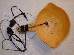
Electronic Ear
Time: I built this project in about two hours,
mainly because I had already made the microphone
circuit.
Cost: The total cost was $0.00. I already had
all of the components made from previous projects, but
if I had to make all the parts over again they would
probably cost less than $5, assuming that you've
already got an earphone, a plastic sieve, and a 9 volt
battery.
Description: This project is a type of electronic
ear I made for my kids.
When I made it I had duct tape over the holes, but
I removed it for the picture. It still works without
the holes covered just not as well. The electric ear
is made from a microphone circuit that I had made a
while back, except that I had to remove the microphone
and place it some distance away from the reflective
surface. The reflective surface is made from a plastic
sieve, because of it's obvious shape and the
convenience of a handle to store the battery and the
circuit in. The placement of the microphone was
simplified by using a wire coat hanger that could
be bent to find the focal point of the reflective
surface. I also added a jack for an earphone/headphone.
I've shown a headphone in the picture but I actually
used an earphone because the electronics didn't power
the headphones very well.
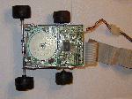
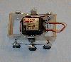
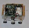
Floppy the Robot
Let me start by saying that the concept of Floppy
the Robot was not conceived by me. I got the idea
and the design from
Floppy the Robot. Any info that you'll probably need
about building a floppy drive robot can be found
at that site.
Time: I would estimate that the time it took me
to build Floppy was about 6 hours. A lot of
that time was spent disassembling the floppy drive and
cleaning it, it was a very old drive taken out of a
very dirty salvaged computer. Once this was done, it
took little time to connect some "Erector" parts for
securing the front drive shaft and wheels. The tether
and power cables were fairly quick as well
Cost: Since I got the floppy drive and cable from
salvaged parts and I already had the "Erector" stuff,
all I really needed was a 7805 voltage regulator chip,
a 9 volt battery, and a 9 volt battery clip. So the
total cost for my "Floppy" was around $6.
Description:
If you can't tell by the picture this little
robot is made from a 3 1/2" floppy drive. Floppy is a
tethered robot, that is controlled from a PC interface.
Right now I don't have any steering hooked up to Floppy
but it shouldn't be very difficult to utilize the
second stepper motor for this.
Stiquito
A Six Legged Robot
Time: The whole project took me about 8 hours
of work to complete. I took several rest periods
between some of the Nitinol wire connections because
they can get very involved, due to their small size
and the detail that they require.
Cost: Stiquito was a kit and not my own creation.
I ordered the kit through my local B. Dalton bookstore.
The Stiquito kit cost about $30, it came with
all the necessary parts and a detailed book that
explained how to build Stiquito, as-well-as how to
make modifications to make different types of Nitinol
powered robots.
Description: What is Stiquito? The Stiquito robot
is a small, inexpensive, six-legged
Nitinol wire (muscle wire)
powered robot that is intended for use as a research
and educational tool. I built this little guy so that I
could learn more about how Nitinol wire works.
There is also a web site called
Stiquito_Advanced Experiments... which is
dedicated to the further study and development of
Nitinol driven robots and devices.
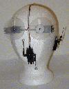
Animatronic Head
Visible Mask
Inner Structure

Time: This project took about a 5 days, at 7-8
hours a day. There were slight modifications made to
the mask, placement of the servos, construction of the
eyes, and the planning of the eye movement. All of
these added to the time required.
Cost: The cost of the entire animatronic head
was only $40. The low cost was mainly because I already
owned the servos, transmitter, and receiver. All I
needed to buy was the mask ($15), the eyes ($2) which
were made from party favor toys, the styrofoam head
($3), the black cloth ($10) and the box ($10).
Description: This is definitely one of my most
favorite projects. This idea came about because I
wanted to create a believable animatronic head, and I
thought that having it in a box lined with black cloth
would help hide any flaws or mistakes that I might
make. The head is manipulated with radio controlled
servos that are linked to the eyes, mouth, and left
ear. A more in-depth description of each of these parts
can be seen below.
-
-
EYES: The eyes were the most difficult part of
the head, because it involved constructing the eyes,
mounting them in the mask, and devising a method for
controlling them. The servos for the eyes
have large plates attached to them, with a vertical
slot cut in each plate to hold a 1 inch pin that is
secured to the back of each eye. When the servo
turns the plate, the pin is held in the slot which
translates the rotational movement to a horizontal one.
-
-
MOUTH: The mouth was not as difficult as the
eyes but it did have some obstacles that I had to
overcome. I first cut the inside of the mouth out to
leave just the lips and toungue. The latex that I cut
out was replaced by black cloth. Having linkages
attached to each side of the servo hub and the lips,
allowed the servo to move the lips up and down when
the hub rotated.
-
-
EAR: The ear was by far the most simplistic. To
make the ear appear to move, I connected a servo
linkage to the crown of the ear from the inside. When
the servo is activated the linkage moves the ear up
and down causing the ear to wiggle. I must say that
it was a pretty good final touch.
Puppet Doll

Time: This doll, turned puppet, took 3 days or
about 20 hours of work. Most of that time was put
into the making the eyes open and close smoothly
and running the small cable wires.
Cost: The cost was $8 for the doll, $3 for the
cables and music wire, $1 for the tubing that the
cables and wire ran through, $0.30 for the dowel
that controls the head movement, and another dollar
for a couple of small magnets that were used to
open and close the eyes.
Description: I was sort of disappointed in the
pictures of the puppet. Being 2 1/2 feet long and
wanting to get the whole thing in the picture, made
it very difficult to get much detail in the picture.
So I also enclosed a picture of the back of the
puppet, but I'm afraid that I left the head sewn up,
which didn't allow any viewing of the internal
operations of the eyes.
-
-
Eyes: The eyes were the type that open when the
doll is picked up by a child. My problem was that I
needed the eyes to open and close when the doll is
standing. Since the eyes would open on their own, I
just needed to make them close when I needed. I did
this by securing a small magnet on a wire below each
eye. When this wire is pushed up the magnets pull a
small piece of metal that is embedded in the eye,
causing the eye to open or close.
-
-
Arms: The arms were made moveable by fastening
two control wires to the inner shoulder, one at the
front and one at the rear. This way when the front
wire is pulled down the arm would go toward the back,
and when the rear wire is pulled down the arm would
go forward. It sort of pivots in the dolls arm socket.
-
-
Head: The head is pretty basic, all I did
was secure a short piece of square dowel to the end
of a long round dowel. This "T" was then glued to the
inside of the dolls head. When the long dowel is
turned the head turns with it. It sounds pretty
simplistic, but it did the trick and it looked
amazingly eerie.
To make sure that the wires, cables and dowels didn't
get caught up on each other, I put each body parts
control wire/cable/dowel in its own plastic tube.
Robot Puppet Hand

Time: The time for this project is a little hard
to estimate. I started this brainchild about a year
ago but didn't truely dedicate any time to it. If I
had to put a number on it I would say that it took me
about 40 hours, but to be honest I haven't completed
it yet. I still need to finish making the rest of the
springs for the knuckles, and reattach the cables to
the fingers and wrist.
Cost: The cost for this was almost zero, the
finger segments were salvage parts as was the main
knuckle joint, all I had to buy was a 1/4 inch bolt,
a few pieces of fine music wire, some jewelers wire
(the kind used in necklaces) and a couple dozen
small round head bolts and nuts. The total cost was
less than $5.
Description: Making a robotic hand first occurred
to me when I was taking apart an old hard drive and
I saw the tracking arms, they looked just like the
fingers of a "Terminator" type robot. All the fingers
except the index and the thumb were made by simply
drilling the appropriate holes and lightly bolting
them together, so they can move freely. The index
finger and the thumb are double layered with the
distal segment sandwiched between them. This way when
the index finger and the thumb are contracted toward
each other the ends actually touch just as human
fingers would. A pretty impressive feat of engineering
if I do say so myself. Once all the fingers were put
together, I used the hard drives hub that the tracking
arms were originally held on, to secure the fingers
together, just like the main knuckle in a hand. This
way each finger could be moved from a central point.
Well the fingers were done, except that the they still
needed some way for them to move. It occurred to me
that if I could move them in one direction, some sort
of spring could move them back to their original
position. I used a small diameter music wire to make
return springs for each small knuckle. Now that the
most dexterous parts of the hand were assembled
together, I needed to make a housing for the cables
that would
eventually be used to pull the fingers closed. I ran
a small jewelers wire down each finger to the last
segment. This wire is run to what would be the palm
of the hand, where a larger cable is connected to it
and routed up what would be the forearm. Here each
of the finger cables are connected to a metallic
ring. The rings are placed on your fingers so that
when you move that finger the corresponding finger
on the robotic hand moves.
Hand Carved Sculptures
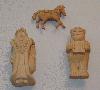
Time: The approximate time for these wooden
sculptures is about a week each, but that's only
a couple of hours a day.
Cost: The cost for the Santas was $1.50 each,
I used the soft pine blocks that you can buy at a
hobby store. There was no cost for the carousel horse,
I used a piece of oak I had in my garage.
Description: I originally started carving
these sculptures because I wanted to make some
Christmas decorations for my wife. So, every year just
before Christmas (about a week) I'd start a new one.
The first one I made was the carousel horse, and by
the way, the last one that I carved out of "oak". Oak
is way too hard of a wood to be much fun. I wish that
I could have had better resolution of the horse so
that you could see the stirrups, saddle, reigns and
the other details. The second one I mad was the tall
Santa
carrying a bag and a staff. I put alot of care in this
one, you can't see it well enough but there is alot
of detail. The hat has the folds of an old cloth hat,
his beard has many long curls, and his shoulder bag
even has a patch with stitching. The third statue
wasn't finished, but he has bifocal glasses, a
balding head, suspenders, fuzzy slippers, and he's
holding an unfinished toy.
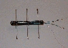
Electronic Rat
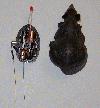
Time: Surprisingly, motorizing the toy rat was
fairly simple. I was able to finish the entire
project in one day. Most of the time was spent on
modifying the tiny gearbox and mounting the motor to
it. I also had to spend some time cutting the rats
body to accommodate the motor. It was quite simple to
make the electronic circuit (batteries, LED).
Cost: The whole thing cost $4. The rat was $1,
the motor was $1, the batteries were $1, the LED and
extra wire was about $1.
Description: While looking through the surplus
stock at a local store I found one of those little
toy rats that you pull backwards and let go. I thought
it might make a cool little project. I had some extra
pager motors and the motors shaft fit perfectly into
the main gear of the rats gear box. It was just a
matter of modifying the gear box, because it has a
tiny gear in it that slides up and down depending on
which way the rat is rolling. This gear needed to be
removed, because when the motor drives the gears
forward the tiny gear is push up and jams the
gearbox. Once the gears and motor were done
I needed to mount the batteries (pretty simple). All
that done, it just didn't seem good enough yet. So I
ended up cutting out the eyes and soldering in an
LED into the circuit. When powered up, the LED lights
up and gives the eyes a bright red glow. When complete
it has a devilish look to it. To switch the power on
and off I ran two long pieces of fine wire out the
"rear" of the rat, when they are hooked together,
the circuit is powered up. I want to add either a
timer circuit or a light detection circuit, so that
it will turn off and on by itself.
Three Wheeled Robot
Radio Controlled
Autonomous
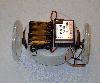
Time: This one took me about two days to
complete. The most time consuming part of my rolling
robot was the making of the coaster wheel assembly.
Cost: The cost to build the radio controlled
wheeled robot was $36.50, but since I already had the
servos the total cost to me was a mere $6.50. The
parts that I got from the hardware store cost $4.50
and the few things that I got from the hobby store
cost $2. For the cost of the autonomous wheeled robot
you would need to add about another $100 for the
BASIC Stamp II board and chip.
Description: I wanted to make a simple little
robot that my kids and I could play with around the
house. I tried to make it out of things that I could
find at my local hardware store. The body is made from
a 4" PVC pipe endcap, with a hole cut out on each side
for the servos. The wheels are made from 3 1/2" PVC
pipe end plugs, with 1/16" tubing wrapped around its
outer rim. The rear coaster assembly is made from a
piece of hanger bent in an "L" shape. Grommets are
used to hold the upper shaft in place so it will
pivot, grommets are also used to hold the coaster
wheel in place. This done, all I needed to do was
secure the receiver to the top of the body. Done.
Then I started thinking that I wanted
it to be more of a thinking robot. I ended up adding
my BASIC Stamp II board to control the robot.
I bought the board and chip from
Parallax Inc., through their "Stamps in Class"
offer. With some help from Ken Gracey at Parallax,
and some others from the "Stamps in Class" news group,
I learned how to program the BASIC chip so that it
could use bumper switches and photo cells to control
the servos. Now it can sense light with the photo cells
I added, while it walks around my house. It's programed
to go toward the light and go around objects that it
bumps into. I plan on adding an infrared sensor from
Radio Shack, and hacking its internal hardware to give
my little walker eyes. Night vision eyes no less.
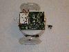
Walking Robot
Radio Controlled
Autonomous
Time: I was rather proud of how fast I was able
to get this little walker up and running. I made the
entire thing in one day. I decided in the morning that
a walking robot would be a nice addition to my
portfolio and by bedtime it was walking around my
house.
Cost: I made the walker robot completely out of
surplus parts I had, so it cost me nothing. If I had
to buy all the parts, the walker would have cost me
about $42, $142 if you want it to be an autonomous.
The servos would have been $15 each so $30
total. The legs probably would have cost around $10
(if you could actually buy them separately). The
plastic for the
body sides could be purchased for $1 with lots of
extra left over, and the wood struts would have cost
less than $1 with lots of extra. Add about another
$100 if you want the BASIC stamp and board that I have
to make it autonomous.
Description: As I mentioned, since I thought
that a walking robot would make a good addition to
my portfolio I decided to make one. I pirated the
legs from a toy robot I had around the house. Then
configured them to work with my servos, instead of the
little DC motors and weak gearing that they already
had. Then I cut out two pieces of thin plastic for the
body walls, placed the servos through holes that I had
cut and secured the servos together. I measured and
cut the four wooden dowels for body support and glued
them in. With the body done I needed to attach the leg
mechanics. There you have it a radio controlled
walking robot. I also wanted to make this robot
autonomous. That was easy enough seeing as I had
already done it to my wheeled robot. All I needed to do
was move the programed board to this robot.
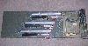
Laser Effects
Lasers & Power Supply
Simple Laser Effect

Time: There really is no way for me to put a
time on this project. I started working with lasers
on my senior project about 3 years ago and I'm still
playing with them and trying new things.
Cost: The galvos were salvaged from a laser
disc player that I purchased from an electronics
salvage store for $50. I have two of this type and
another more expensive type that cost about $60.
I got my three lasers from salvaged bar code scanners.
The type you would find used with cash registers in
a grocery store. Each scanner cost me $25, but I had
to piece everything out myself. I also used the power
supply in the scanners to power the lasers, so that
was included in the $25. The circuitry was made with
breadboards so that I could make frequent changes.
The total cost for that was $20 and the cost for the
miscellaneous electronics was around $20. That's a
total of $275. Seems like a lot, but I bought most
of this stuff over a long period of time.
Description: Since I wrote a description of my
laser graphics project in my senior project
description, I'll just tell some examples of what I
like to do with my lasers. On Halloween I'll setup one
or two lasers with a sine/cosine generator, and have
them display spirograph like patterns on the walls or
the yard. I often power a laser up and try projecting
through different mediums, like glass gradients.
These can often produce very unexpected results.
Smoke is always fun. By making the galvo project the
laser in a constant circular pattern through a cloud
of smoke, you create a tunnel effect. The tunnel
effect isn't easily explained, but once seen, it's
difficult to forget.
Senior Project
Interactive Laser Graphics
Block Diagram
Motherboard Schematic


Time: The time I spent on my senior project was
nearly 2 years. Most of this time was spent on research
of the workings of lasers and the many IC chips that I
would need for the circuits I planned on making.
Building the actual project went rather fast once I
knew how the components worked.
Cost: The cost for my senior project as estimated
on my senior project write-up was $500, but that was
the projected cost of a fully complete system. My
system consisted of 4 lasers ($100), 2 galvonometers
($50), 2 power supplies ($25), many IC chips ($10,
being a student many companies offered me free chips),
and assorted electronics ($30). I was required to
construct my own mother board to operate my senior
project, so that was an additional $100. That's a
total of $315 for my senior project.
Description: If you are really interested in
reading about my senior project, the "Interactive Laser
Graphics" write-up can be seen by clicking the laser
icon.
Lastly, if someone might be intersted in seeing
my schematics or the sample program I wrote, please
write and let me know. I'll try to get them out to
you, but it may take a little while, because my senior
project write-up was 21 pages long.
My RC Transmitter

Description: It's a 6 channel transmitter made
for helicopters, so all of its channels are
reversible. This is to allows the operator to fly
the helicopter upside down, without having to operate
the controls in reverse. This also comes in very handy
when operating special effects with multiple servos.
If you would like to see a text format version of my
resume just click on the dinosaur.